3.4.5 Faraday’s Law & Electromagnetic Waves
Maxwell’s Theory Suggests Light is an Electromagnetic Wave
Celebrating the first 1000 subscribers to Fields & Energy!
Thank you all for joining me on this voyage of discovery.
The final piece of the electromagnetic puzzle is Faraday’s Law, that a changing magnetic field induces an electric field. Put the pieces together and a fascinating picture emerges. A changing electric field makes a magnetic field – the effect described by Maxwell’s “displacement current.” A changing magnetic field makes an electric field – the effect discovered by Faraday.
What happens if both change at the same time?
The electric and magnetic fields merge together, changing synchronously, and propagating off into the distance. An “electromagnetic wave” is born.
Faraday grasped that electric and magnetic effects are non-local: they occur throughout the space surrounding charges and currents. Faraday intuited that these effects must somehow propagate from one place to another, but he couldn’t describe why, and his experimental techniques were too crude to see such effects in action and tease out how they behave.
Starting from Faraday’s premises, Maxwell demonstrated that electric and magnetic effects are not only non-local, but also progressive. They move from place to place. In Maxwell’s theory, actions don’t just happen at a distance. Rather, electric and magnetic fields work together to impose forces and convey energy from one place to another.
Maxwell’s theory would require considerable elaboration from his successors, primarily Oliver Heaviside (1850–1925) and Heinrich Hertz (1857–1894). Many more subtle implications were still unclear. What was clear, however, was that Maxwell’s theory predicted electric and magnetic fields work together to make electromagnetic waves.
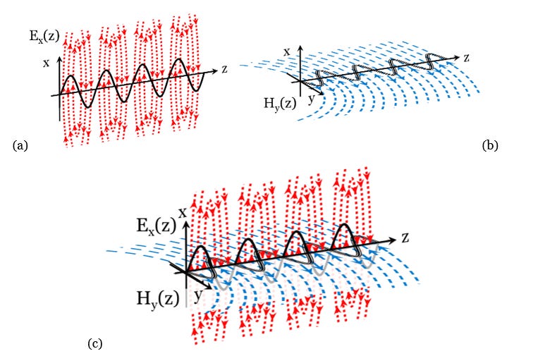
An electric wave and a magnetic wave, cooperate at right angles with respect to each other, to form an electromagnetic wave as in Figure 3.28. For simplicity, the magnetic field lines are shown only in the y-z plane, and the electric field lines are depicted only in the x-z plane. While the field lines must all ultimately form closed loops, this figure necessarily truncates and crops out the big picture to focus on local details. In addition, the diagram neglects certain “near-field” effects to be addressed later. The field intensity depends upon the density of the field lines.

That there might be a connection between light and electromagnetism had been suspected for some time. Not surprisingly, Faraday was the first to find experimental evidence that light might be electromagnetic. Faraday took “polarized” light (light consisting of waves whose electric fields oscillate in a fixed plane), and, by passing it through materials in a region with a strong magnetic field, he found that the light would twist. In other words, the plane of polarization would rotate [[i]]. This suggested that light might be electromagnetic.
In 1857, Gustav Kirchhoff (1824-1887) measured the speed at which electrical signals travel in a telegraph wire. The speed of an electric wave turned out to be remarkably close to the speed of light [[ii]]. Maxwell’s equations predicted that these waves would travel at a speed given by an algebraic combination of some basic electromagnetic constants whose value turned out to be the same as the speed of light, within the margin of experimental error. These constants? The “electric permittivity” and the “magnetic permeability.”
Next time: 3.4.6 Permittivity & Permeability: Mr. Heaviside’s “Not So Helpful Terms”
Follow Online:
You may follow me online in other places as well:
Telegram: 𝔸𝕖𝕥𝕙𝕖𝕣𝕔𝕫𝕒𝕣'𝕤 𝔸𝕖𝕥𝕙𝕖𝕣𝕤𝕥𝕣𝕖𝕒𝕞
Gab: @aetherczar
Twitter: @aetherczar
Amazon: Hans G. Schantz
References
[[i]] Michael Faraday, Experimental Researches in Electricity, Vol. III, § 2146-2242 (New York: Dover Publications, Inc., 1965) pp. 1-26. Originally published 1855. See also Whittaker, Op.Cit. pp. 190-193. This is the so-called "Faraday rotation."
[ii] Whittaker, Op.Cit. pp. 230-232.


I am now in a position where I mostly understand the math of AC power, although I could not easily replicate it. So I am broadly ok with the Euler Equation, and P=V x I and all the sine wave and phase angle complications and real and reactive power, P and Q diagrams and phase angle and power factor, etc etc. I can even broadly understand phasors and phasor algebra. The problem I always had (until recently) was understanding why or how power (energy flux) actually flowed, and in what direction. I never found P=V x I and its units Watts, Volts and Amps very intuitive. And because I don't know the Maxwell equations I cant relate it all. What finally got me going in the right direction was learning about the Poynting Vector, which I had NEVER heard about before. Basically I believe the Poynting Vector is related to the Maxwell equations and basically says that energy flux is basically the cross product of the electric and magnetic fields, and once I played with this a bit, I could see how the AC voltage and current waves (and their corresponding electric and magnetic fields, at right angles) could show that power flows in one consistent direction (oscillating of course at twice the line frequency) and if the phase angle shifted into another quadrant, the cross product reverses direction and power goes the other way. So on the PQ diagram this is why in two quadrants the power is positive and in the other two is negative and all that describes in the direction of energy flux in the line. The thing about the Poynting Vector is that its usually used to describe power flow in wireless transmission, but I am sure it also applies to wired power, AC or even DC.
Any comments?
Wow, I am super happy I found you. I am keen to learn and have lot of pending questions!