

Near-Field Technology - An Emerging RF Discipline
How Does My 2006 Paper Hold Up?

In 2006, I was invited to Nice, France to deliver one of the two keynote addresses at the first European Conference on Antennas and Propagation (EuCAP). The topic I chose was Near-Field Technology - An Emerging RF Discipline, and with some contributions from my colleague, James Fluhler, I drafted this paper. In republishing it here, I corrected a few typos I spotted. Also, I added an afterward to share my thoughts on how well my predictions held up.
ABSTRACT
This paper explains and surveys the emerging RF discipline of near-field technology. First, this paper defines what is meant by the “near field.” Then, this paper presents a brief history of near-field technology from Faraday to the present day. In particular, this paper focuses on recent advances in near-field technology for applications like Near Field Communications (NFC), Radio Frequency Identification (RFID), and Real Time Location Systems (RTLS). Finally, this paper will discuss the extension of propagation laws and antenna gains to the near-field regime.
1. INTRODUCTION
The “leading edge” of radio frequency (RF) practice moves to increasingly higher and higher frequency in lock step with advances in electronics technology. The most commercially significant RF systems are those operating at microwave frequencies and above, such as cellular telephones and wireless data networks. Microwave frequencies have the advantage of short wavelengths, making antenna design relatively straightforward, and vast expanses of spectrum, making large bandwidth, high data rate transmissions possible.
There are many applications, however, that do not require large bandwidths. These include radio frequency identification (RFID) systems, real time locating systems (RTLS) and low data rate communications systems, such as hands free wireless mikes or other voice or low data rate telemetry links. For applications like these, lower frequencies have great utility:
Lower frequencies tend to be more penetrating than higher frequencies.
Lower frequencies tend to diffract around objects that would block higher frequencies.
Lower frequencies are less prone to multipath.
Lower frequencies roll-off more quickly than higher frequencies allowing relatively small cell sizes and more efficient re-use of spectrum.
An amazing and often overlooked world of RF phenomena lies within about a half wavelength of an electrically small antenna. This realm is known as the “near-field zone.” The near-field zone is usually neglected by RF scientists and engineers because typical RF links operate at distances of many wavelengths where near-field effects are utterly insignificant. “Near- field” means different things in different contexts. Fortunately there is an excellent article available that sorts through the various definitions of near-field and provides some guidance [1]. Harold Wheeler introduced the classic definition of the “radiansphere” to denote the boundary between near- and far-field regions [2]. The radiansphere is a spherical shell of radius λ/2π around a small dipole antenna. This is the distance at which the induction and radiation terms are equal in magnitude. Inside, the induction terms dominate. Outside, the radiation terms dominate. Although the radiation terms dominate outside the radiansphere, the induction terms still play a significant role out to a half-wavelength or even farther.
First, this paper will present a brief history of near-field technology from Faraday to the present day. In particular, this paper focuses on recent advances in near-field technology for applications like Near Field Communications (NFC), Radio Frequency Identification (RFID), and Real Time Location Systems (RTLS). Finally, this paper will discuss the extension of propagation laws and antenna gains to the near-field regime.
2. NEAR-FIELD WIRELESS: A BRIEF HISTORY
Micheal Faraday (1791-1867) and Joseph Henry (1797-1878) independently discovered induction in the 1830’s. Since Faraday was the first to publish, he is generally given credit for the discovery. Faraday’s work led not only to Maxwell’s Equations, but also to applications including electric motors and electric generators. Understanding induction also led to the discovery of a practical system of telegraphy. The first commercial “wireless” systems were actually near-field or inductive coupled systems that allowed operators on board a train to communicate using a telegraph wire parallel to the train track. In fact, the first induction wireless system was patented by William Smith in 1881 [3]. Granville T. Woods also patented a more practical induction telegraph in 1887 [4]. Neither scheme enjoyed any significant commercial success, however. Figure 1 shows the cover pages of these patents.

As technology progressed and as the discoveries of Hertz, Lodge, and Marconi shifted interest to long distance communication, near-field wireless was largely ignored in favor of far-field wireless. In his 1932 text, Radio Engineering, Frederick Emmons Terman famously observed, “An understanding of the mechanism by which energy is radiated from a circuit and the derivation of equations for expressing this radiation quantitatively involve conceptions that are unfamiliar to the ordinary engineer [5].” If the application of Maxwell’s equations to far-field radiation problems was beyond practical everyday engineers, the further subtleties of near-field phenomena were even more arcane and esoteric.
By the time of the Second World War, radio engineering experienced a renaissance. Maxwell’s Equation assumed their rightful place as the foundation of RF engineering, and RF engineering became not only an art but also a science. Interest in microwaves for radar applications pushed RF technology to such high frequencies that near-field RF remained a neglected and poorly understood backwater. Still, radar technology also introduced the concept of reflecting RF energy from a passive target, even using the reflected power as a communications medium [6].
Now with rapidly growing demands for short range communications links, non-line-of-sight inventory control, and real-time location information, near-field wireless is emerging as the best solution to a variety of significant problems.
3. THE NEAR-FIELD INDUSTRY
Near-field RF technology is applicable in a number of important applications. This section will survey the use of near-field RF for short range communications, for inventory control using passive tags (RFID), and for Real-Time Locating Systems (RTLS).
3.1 Near Field Communication
Aura Communications was formed in 1995 to exploit near-field behavior in the context of short-range communication systems including wireless hands-free earpieces and headphones [7] (see Figure 2).

Aura Communications “LibertyLink™” magnetic induction data transfer system provides 410kb/s data rates at 3m ranges operating at 13.56 MHz. Sony, Nokia, and Phillips teamed to form the Near-Field Communication (NFC) Forum, to promote similar technology [8]. In 2003, a global standard for near-field communication was adopted [9]. Key applications are anticipated to include contactless payments, secure verification and validation, and hands-free earpieces and headphones.
3.2 Radio Frequency Identification (RFID)
In the 1960’s companies like Checkpoint systems, Inc. [10] and Sensormatic [11] introduced Electronic Article Surveillance (or EAS) systems. These “one-bit” tags are used for inventory control and deterrence and detection of shoplifters. With typical ranges of 1-3m (3-10ft), RFID technology as currently practiced today goes back at least to the early 1970’s. Martin Cardullo was awarded a patent in 1973 for a passive transponder capable of modulating a reflected signal with stored data (see Figure 3) [12].

Additional information and references pertinent to the development of RFID are available in an online article [13]. The burgeoning area of RFID technology exploits near-field physics to enable short-range, low-cost tags with the potential to revolutionize supply-chain management and inventory control. With the recent adoption by WalMart and other large retailers of RFID technology, this alone promises to be a $5 billion industry by 2007 [14]. Figure 4 shows a typical RFID tag used in an Electronic Product Code (EPC) application.

3.3 Real-Time Location Systems (RTLS)
Near-field behavior is also the foundation for a breakthrough in wireless tracking and positioning pioneered by the Q-Track Corporation [note, I was a co-inventor of the technology, co-founder of the company, and served as CTO]. “Near-field electromagnetic ranging” or NFER™ technology allows for positioning with an accuracy approaching one foot at ranges up to 250 feet or more, even in complicated indoor propagation environments [16]. Figure 5 shows a tag, receiver, and tracking GUI for this system.

The emerging near-field industry is poised for explosive growth, but places unique demands on antenna (or sensor) technology. Near-field sensors and tags are generally not characterized with respect to gain, so there is no way for engineers to mathematically define or evaluate a link equation. The near-field industry relies on trial-and-error and empirical approaches to antenna design [17]. There is a significant disconnect between theory and practice which means there are similarly significant opportunities for engineers and scientists in both industry and academia.
4. NEAR-FIELD ANTENNAS AND PROPAGATION
The dipole field equations provide a relatively simple model of near-field behavior. A small electric antenna (like a whip) is modeled by an electric dipole and a small magnetic antenna (like a loop or loopstick) is modeled by a magnetic dipole. The traditional Friis Propagation Law describes the received power (PRX) in terms of transmit power (PTX), and the transmit and receive antenna gains (GTX and GRX, respectively). Friis Law assumes far-field propagation, with a range typically many wavelengths apart. In the near-field region, signal strength varies much more rapidly than for far field propagation. There are actually two different link equations – one between “like” antennas (electric-electric or magnetic-magnetic) and one between “unlike” antennas (magnetic-electric or electric-magnetic) [18]. In terms of the wave number (k = 2π⁄λ), the transmit power (PTX), the like antenna received power is:

and the unlike antenna received power is:

Near-field signals roll-off much more quickly than the more familiar far field signals. Signals between like antennas (electric to electric or magnetic to magnetic) roll off at 60 dB per decade. Signals between unlike antennas (electric to magnetic or vice versa) roll off at 40 dB per decade. By comparison, far-field signals roll-off at 20dB per decade in free space. These near-field channel relations are provided in Figure 6. Some interesting physics comes into play in the near field with respect to antenna gain and phase behavior.

Figure 6 indicates that under some circumstances path gain may be greater than 0 dB. This means that the receive power could theoretically be greater than the transmit power. Since conservation of energy must apply to RF links, this means that antenna gain cannot be arbitrarily large. There necessarily exists a limit to antenna gain as a function of antenna size.
4.1 Gain Versus Size for Electrically Small Antennas
Our approach borrows on the concept of an antenna “boundary sphere” introduced by Wheeler [19] and extended upon by Chu [20]. A boundary sphere is the smallest sphere within which an antenna may be enclosed. Thus the radius of the boundary sphere defines the characteristic size of an antenna. A matched pair of antennas with boundary spheres of radius R may be no closer than d = 2 R without overlapping, as shown in Figure 7.

Taking this as the limit, we can apply the near-field propagation equation for like antennas (Eq. 1) to establish a limit for antenna gain versus size:

We measured gain of a variety of antennas by comparing the received power of the antenna under test to the received power of a calibrated antenna (an EMCO 6509 loop). Figure 8 presents the results. [This only works in the limit of weakly-coupled antennas, however].

4.2 Near Field Phase Relations
RF engineers and scientists often think of radio signals as a wave propagating inexorably away from a transmit antenna. An electromagnetic wave is not a single wave, however. Rather, an electromagnetic wave is a superposition of an electric wave and a magnetic wave. In the far field, many wavelengths away from a transmit antenna, this distinction is not terribly important, because the electric and magnetic waves move in lock step with perfectly synchronized phase. In the near field, within about a half wavelength or so from an electrically small antenna, the electric and magnetic field phases radically diverge. Close to an electrically small antenna, these fields are in phase quadrature, i.e. 90 degrees out of phase.
A simple thought experiment involving electromagnetic energy flow establishes why the fields are in quadrature close to an electrically small antenna and in phase far away. The Poynting vector (S = E × H) is the measure of the energy flux around the hypothetical small antenna. If the electric and magnetic fields are phase synchronous, then when one is positive, the other is positive and when one is negative the other is negative. In either case, the Poynting flux is always positive and there is always an outflow of energy. This is the radiation (or “real power”) case. If the electric and magnetic fields are in phase quadrature, then half the time the fields have the same sign and half the time the fields have opposite signs. Thus, half the time the Poynting vector is positive and represents outward energy flow and half the time the Poynting vector is negative and represents inward energy flow. This is the reactive (or “imaginary power”) case. Thus, fields in phase are associated with far field radiation and fields in quadrature are associated with near-field quadrature. As this paper will describe in detail, there is a gradual transition from near-field phase quadrature to far field phase synchronicity.

The phase relationships around small antennas were discovered by Heinrich Hertz in the 1880’s (see Figure 9) [21]. These phase relationships are the basis of a novel wireless tracking system pioneered by Q-Track using Near-Field Electromagnetic Ranging (or NFER) technology [22].
The difference in phase angle (in units of degrees) between the electric and magnetic components of a radio wave is described by [23]:

Repeated trials of a prototype transmitter and receiver in open field testing yielded results in close agreement with theoretical predictions. The prototype hardware operated at a frequency of 1295kHz where λ = 231.5m.
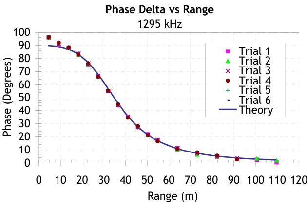
Figure 10 overlays six experimental trials with the theoretical prediction. The theoretical prediction breaks down within about 3 m where the antenna dimensions become a significant fraction of the range. In this limit, the small antenna approximation underlying the theoretical phase behavior is no longer valid.
5. Conclusions
This paper provides a brief overview of near-field RF technology with special reference to antennas and propagation. Long regarded as a technical backwater, interest in low frequencies for such applications as NFC, RFID, and RTLS are driving a renaissance in near-field RF.
Derivation of the near-field link equations and an understanding of near-field phase relations provide a foundation for understanding the behavior of antennas and propagation in the near-field context, but there is much more work waiting to be done.
Acknowledgements:
This work was supported in part by the NSF under grant OII-0539073.
Afterword (2024):
RFID and NFC have continued their growth since 2006. NFC did not find much traction in the wireless headset market contrary to my expectations, however. FreeLinc acquired Aura Communications in 2007. They market wireless headsets for police and tactical customers. See: https://www.freelinc.com/. The broader commercial market for wireless headsets is largely dominated now by Bluetooth - a more traditional 2.4 GHz wireless technology. NFC has found a sizeable niche in contactless wireless payments and other short-range secure links.
I was a co-founder of Q-Track and a co-inventor of Q-Track’s NFER location systems. NFER real-time location was a technical success, delivering highly accurate non-line-of-sight tracking. For instance, at one point about a third of U.S. nuclear plants used Q-Track’s RTLS-based Dosimulation™ systems for radiation worker training. The company failed to achieve a sizeable commercial presence, however. Q-Track was acquired by GaN Corporation in 2019, and GaN Corporation discontinued the NFER RTLS product line.
As noted, the antenna limit I derived is only valid in the weakly-coupled limit.
I contributed to another more thorough paper on how near-field link work in 2013.
References:
[1] Charles Capps, “Near-field or Far Field,” EDN, August 16, 2001, pp. 95-102.
[2] Harold H. Wheeler, “The Radiansphere Around a Small Antenna,” Proceedings of the IRE, Vol. 47, August 1959, pp. 1325-1331.
[3] William Smith, “Car Telegraph,” U.S. Patent 247,127, September 13, 1881. L.J. Phelps is sometimes credited with the first practical induction telegraph but his patent (U.S. Patent 307,984) appears to work on the principle of direct conduction with a sliding contact.
[4] Granville T. Woods, “Induction telegraph system,” U.S. Patent 373,915, November 29, 1887.
[5] Frederick Emmons Terman, Radio Engineering, New York: McGraw-Hill, 1932, p. 494.
[6] Harry Stockman, “Communication by Means of Reflected Power,” Proceedings of the IRE, October 1948, pp. 1196-1204.
[7] See http://www.auracomm.com/ for additional information. [Dead link. FreeLinc acquired Aura Communications in 2007. See https://www.freelinc.com/.]
[8] See http://www.nfc-forum.org/for more details.
[9] http://www.ecma-international.org/news/Ecma-340-NFCIP-1.htm.
[10] See http://www.checkpointsystems.com/default.aspx?page=eas for additional information.
[11] See http://www.sensormatic.com/ for additional information.
[12] Mario Cardullo, et al, “Transponder apparatus and system,” U.S. Patent 3,713,148, January 23, 1973.
[13] Jeremy Landt and Barbara Catlin, “Shrouds of Time: The History of RFID,” AIM, Inc., October 2001. See: https://transcore.com/wp-content/uploads/2017/01/History-of-RFID-White-Paper.pdf
[14] Jeff St. John, Tracking a Revolution, TriCity Herald, May 29, 2005.
[15] Wikipedia article - RFID.
[16] See http://www.q-track.com/ for more on NFER™ technology. Full disclosure – Dr. Schantz is Chief Scientist of the Q-Track Corporation.
[17] See, for instance, the excellent, but non-mathematical work of J.A. Goulbourne, HF Antenna Cookbook, Texas Instruments. See: https://www.ti.com/lit/an/scba033/scba033.pdf
[18] Hans Schantz, “A Near-field Propagation Law and a Novel Fundamental Limit to Antenna Gain versus Size,” Proceedings of the IEEE APS Conference, Washington, D.C., July 2005. Some of the discussion of the present paper was excerpted from this reference.
[19] Harold A. Wheeler, “Fundamental Limitations of Small Antennas,” Proc. IRE, 35, 1947, pp. 1479-1484.
[20] L.J. Chu, “Physical Limitations of Omni-Directional Antennas,” Journal of Applied Physics, 19, December 1948, pp. 1163-1175.
[21] Heinrich Hertz, Electric Waves, London: Macmillan and Company, 1893, p. 152.
[22] Hans Schantz and Robert DePierre, “System and Method for Near Field Electromagnetic Ranging,” U.S. Patent 6,963,301, November 8, 2005.
[23] Hans Schantz, “Near Field Phase Relationships,” Proceedings of the IEEE APS Conference, Washington, DC, July 2005. The discussion of this section is excerpted in part from this paper.
Held up pretty well. At higher frequencies, selective fading and diffraction are larger problems than anticipated. A lot of trees and man-made objects have features that are easy multiples of millimeter wave signals. Lower frequency makes for more tractable diffraction effects; it's the difference between building edge and edge, trim, and fencing, with decorative conifers.
We present a paper on nearfield EM wave propagation that has just been peer reviewed and accepted for publication by the International Journal on Communications Antenna and Propagation (IRECAP). In this paper we present an experiment where a longitudinal Electric field pulse is propagated to a detector in the nearfield, and no time delay was observed. The results are predicted by EM theory using Maxwell's equations and are presented in the paper. The results show that the front speed or information speed of EM fields is instantaneous. Here is preprint of the paper:
https://www.techrxiv.org/doi/full/10.36227/techrxiv.170862178.82175798/v1
In a previous paper, the nonlinear phase vs distance curve (dispersion curve) for the transverse electric field, also shown in this post by Hans Shantz, was observed experimentally by transmitting a radio wave between 2 dipole antennas as the antennas were moved from the nearfield to the farfield. Applying well known phase speed and group speed relations to the dispersion curve, the results showed that the speed of the resultant fields propagate instantaneously in the nearfield, and reduce to about speed c at about 1 wavelength from the source. The speed of the fields then converge asymptotically to speed c, but are never exactly speed c, even at astonaumical distances from the source. The results match very well with those predicted by EM theory. Here is preprint of this paper:
https://arxiv.org/abs/physics/0603240
This research shows that the speed of light is not a constant as once thought, and this has now been proved by Electrodynamic theory and by Experiments done by many independent researchers. The results clearly show that light propagates instantaneously when it is created by a source, and reduces to approximately the speed of light in the farfield, about one wavelength from the source, and never becomes equal to exactly c. This corresponds the phase speed, group speed, and information speed. Any theory assuming the speed of light is a constant, such as Special Relativity and General Relativity are wrong, and it has implications to Quantum theories as well. So this fact about the speed of light affects all of Modern Physics. Often it is stated that Relativity has been verified by so many experiments, how can it be wrong. Well no experiment can prove a theory, and can only provide evidence that a theory is correct. But one experiment can absolutely disprove a theory, and the new speed of light experiments proving the speed of light is not a constant is such a proof. So what does it mean? Well a derivation of Relativity using instantaneous nearfield light yields Galilean Relativity. This can easily seen by inserting c=infinity into the Lorentz Transform, yielding the GalileanTransform, where time is the same in all inertial frames. So a moving object observed with instantaneous nearfield light will yield no Relativistic effects, whereas by changing the frequency of the light such that farfield light is used will observe Relativistic effects. But since time and space are real and independent of the frequency of light used to measure its effects, then one must conclude the effects of Relativity are just an optical illusion.
Since General Relativity is based on Special Relativity, then it has the same problem. A better theory of Gravity is Gravitoelectromagnetism which assumes gravity can be mathematically described by 4 Maxwell equations, similar to to those of electromagnetic theory. It is well known that General Relativity reduces to Gravitoelectromagnetism for weak fields, which is all that we observe. Using this theory, analysis of an oscillating mass yields a wave equation set equal to a source term. Analysis of this equation shows that the phase speed, group speed, and information speed are instantaneous in the nearfield and reduce to the speed of light in the farfield. This theory then accounts for all the observed gravitational effects including instantaneous nearfield and the speed of light farfield. The main difference is that this theory is a field theory, and not a geometrical theory like General Relativity. Because it is a field theory, Gravity can be then be quantized as the Graviton.
Lastly it should be mentioned that this research shows that the Pilot Wave interpretation of Quantum Mechanics can no longer be criticized for requiring instantaneous interaction of the pilot wave, thereby violating Relativity. It should also be noted that nearfield electromagnetic fields can be explained by quantum mechanics using the Pilot Wave interpretation of quantum mechanics and the Heisenberg uncertainty principle (HUP), where Δx and Δp are interpreted as averages, and not the uncertainty in the values as in other interpretations of quantum mechanics. So in HUP: Δx Δp = h, where Δp=mΔv, and m is an effective mass due to momentum, thus HUP becomes: Δx Δv = h/m. In the nearfield where the field is created, Δx=0, therefore Δv=infinity. In the farfield, HUP: Δx Δp = h, where p = h/λ. HUP then becomes: Δx h/λ = h, or Δx=λ. Also in the farfield HUP becomes: λmΔv=h, thus Δv=h/(mλ). Since p=h/λ, then Δv=p/m. Also since p=mc, then Δv=c. So in summary, in the nearfield Δv=infinity, and in the farfield Δv=c, where Δv is the average velocity of the photon according to Pilot Wave theory. Consequently the Pilot wave interpretation should become the preferred interpretation of Quantum Mechanics. It should also be noted that this argument can be applied to all fields, including the graviton. Hence all fields should exhibit instantaneous nearfield and speed c farfield behavior, and this can explain the non-local effects observed in quantum entangled particles.
*YouTube presentation of above arguments: https://www.youtube.com/watch?v=sePdJ7vSQvQ&t=0s
*More extensive paper for the above arguments: William D. Walker and Dag Stranneby, A New Interpretation of Relativity, 2023: http://vixra.org/abs/2309.0145
Dr. William Walker - PhD in physics from ETH Zurich, 1997